

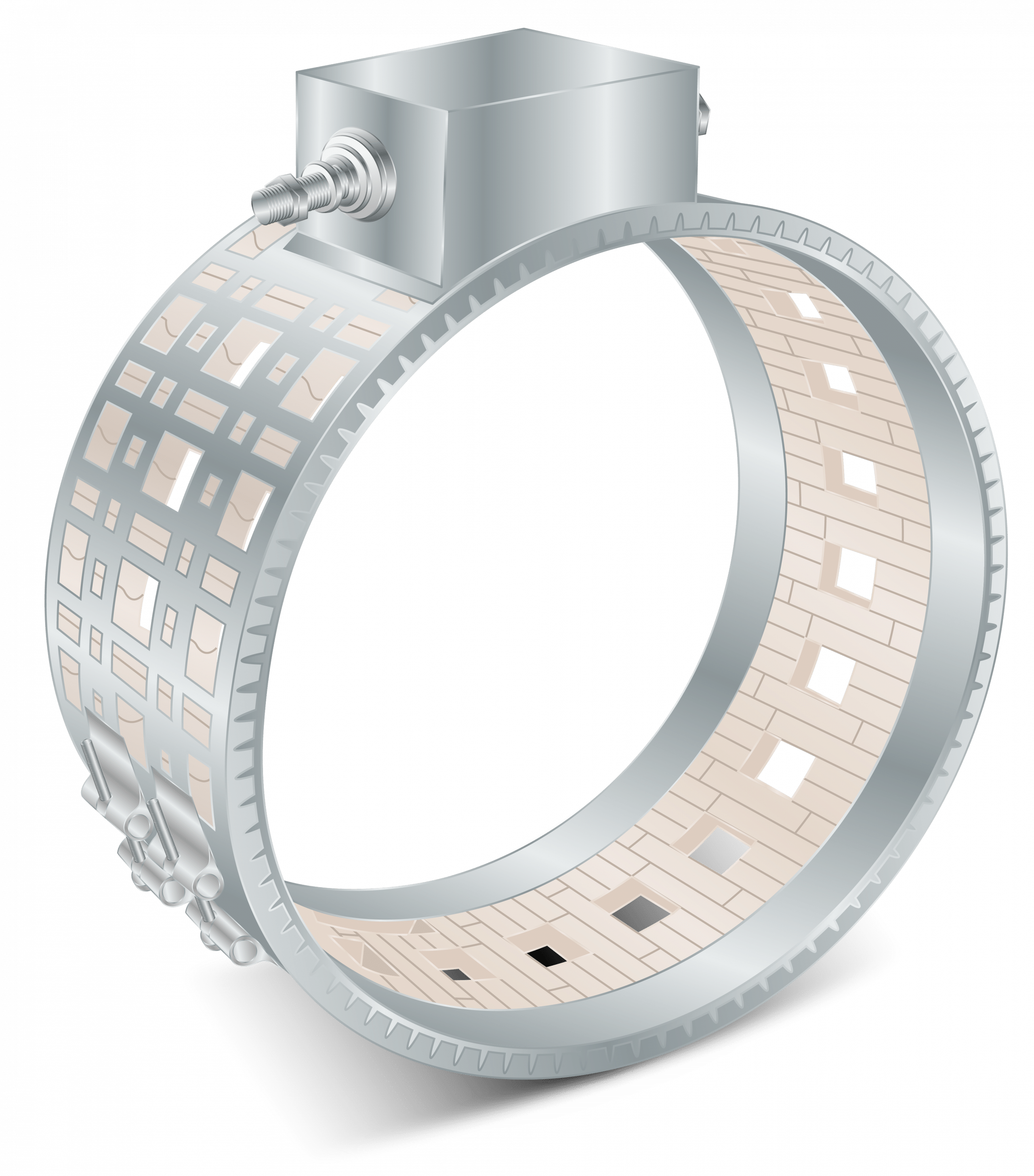
Ceramic band heaters are industrial heating elements that are designed with spirally wound inner resistance coils that are evenly threaded through interlocking insulated ceramic “tiles”. The ceramic core, or “mat” of tiles, is housed beneath a stainless steel sheet with serrated edges that fold over to secure the ends. A protective inner liner (to be removed at installation) is used to secure the placement of the tiles. This design offers a flexible heating system that is efficient in transmitting conduction and radiated heat.
The heat of the ceramic band originates from the inner coils that conduct heat at high temperatures. The heated coils evenly deliver heat through the ceramic tiles, which then radiate energy to the barrel. We offer a variety of ceramic band styles, from standard to custom configurations. When choosing a ceramic band heater, it’s important to select a heater that best matches the wattage requirements to decrease the frequency of cycling and temperature overshooting, and thus increase the life of the heater.
When installing a ceramic band heater to replace a non-insulated heater, it is recommended to decrease the total operating wattage by around 15-20 percent. If you don’t see a band heater style that meets your needs, please contact us at 416-675-7329 or email us at sales@mpimorheat.com,
Ceramic band heaters are commonly used in a variety of industrial applications such as extruders, injection molding machines, blown film dies, and other cylinder heating applications.
| Maximum Operating Temperature | 1600°F | |
| Maximum Voltage | 600 Volts | |
| Maximum Amps | 30 Amps | |
| Wattage Tolerance | +5%, -10% | |
| Maximum Recommended Watt Density | 55 W/in² | |
| Minimum Diameter | 1.5 inches | |
| Width Range | 0.8″-26″ (20mm-660mm) | |
| Heater Thickness | ||
| Heater Type | Nominal Thickness | Insulation Thickness |
| Standard | 5/8″ | 1/4″ |
| Extra Insulation | 15/16″ | 1/2″ |
| Construction Types | ||
| Picture | Type | Notes |
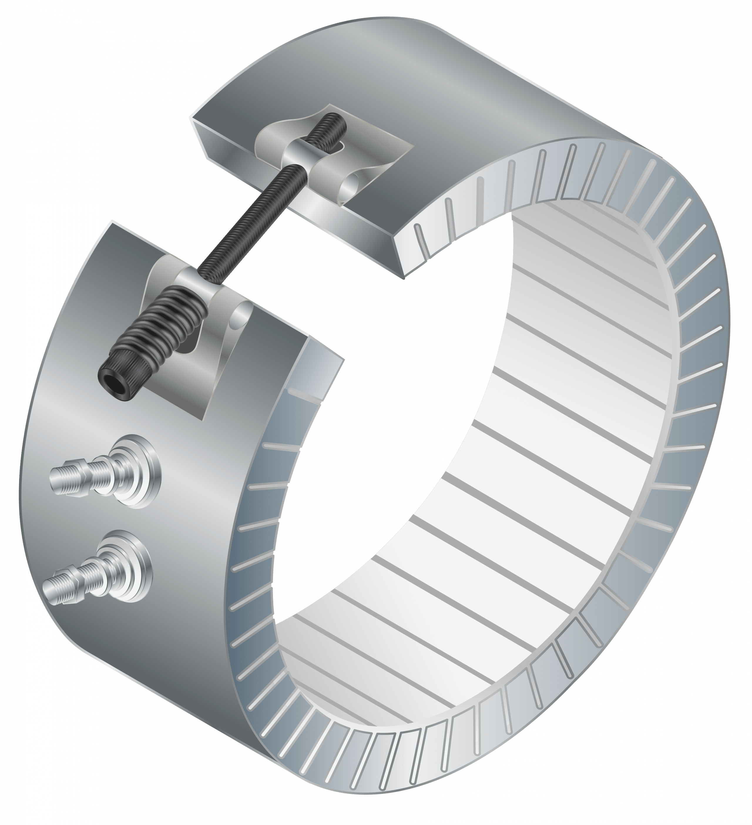 | C1 | The One-Piece Ceramic Band heater construction is the standard design most often specified by OEMs and processors. One-Piece bands can be made with any insulation, clamping and termination style. |
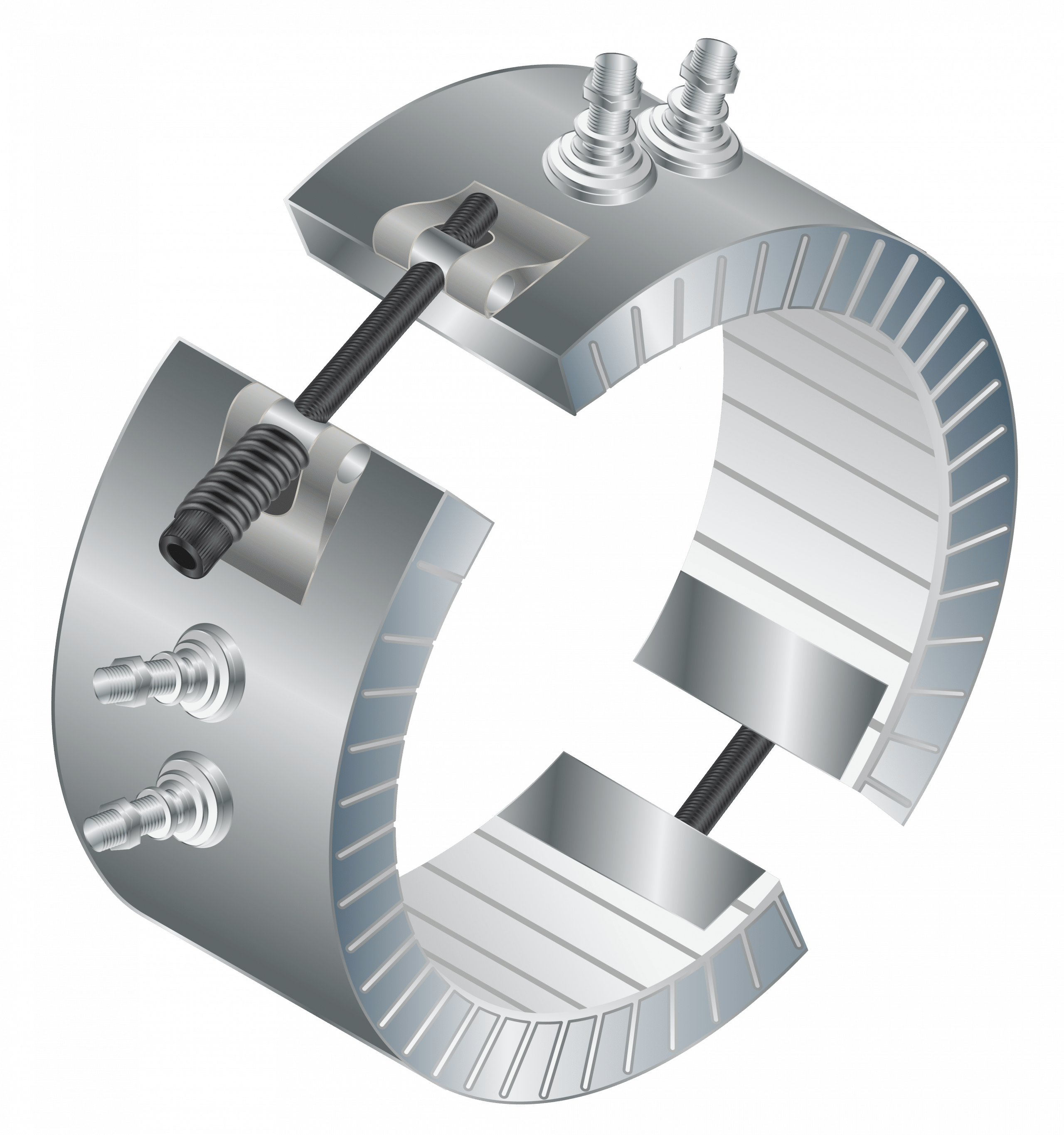 | C2 | The Two-Piece Ceramic Band heater construction is commonly used on barrels with diameters greater than 21″ or when it is not convenient to use a one-piece band. Two-Piece bands can be made with any insulation, clamping and termination style. |
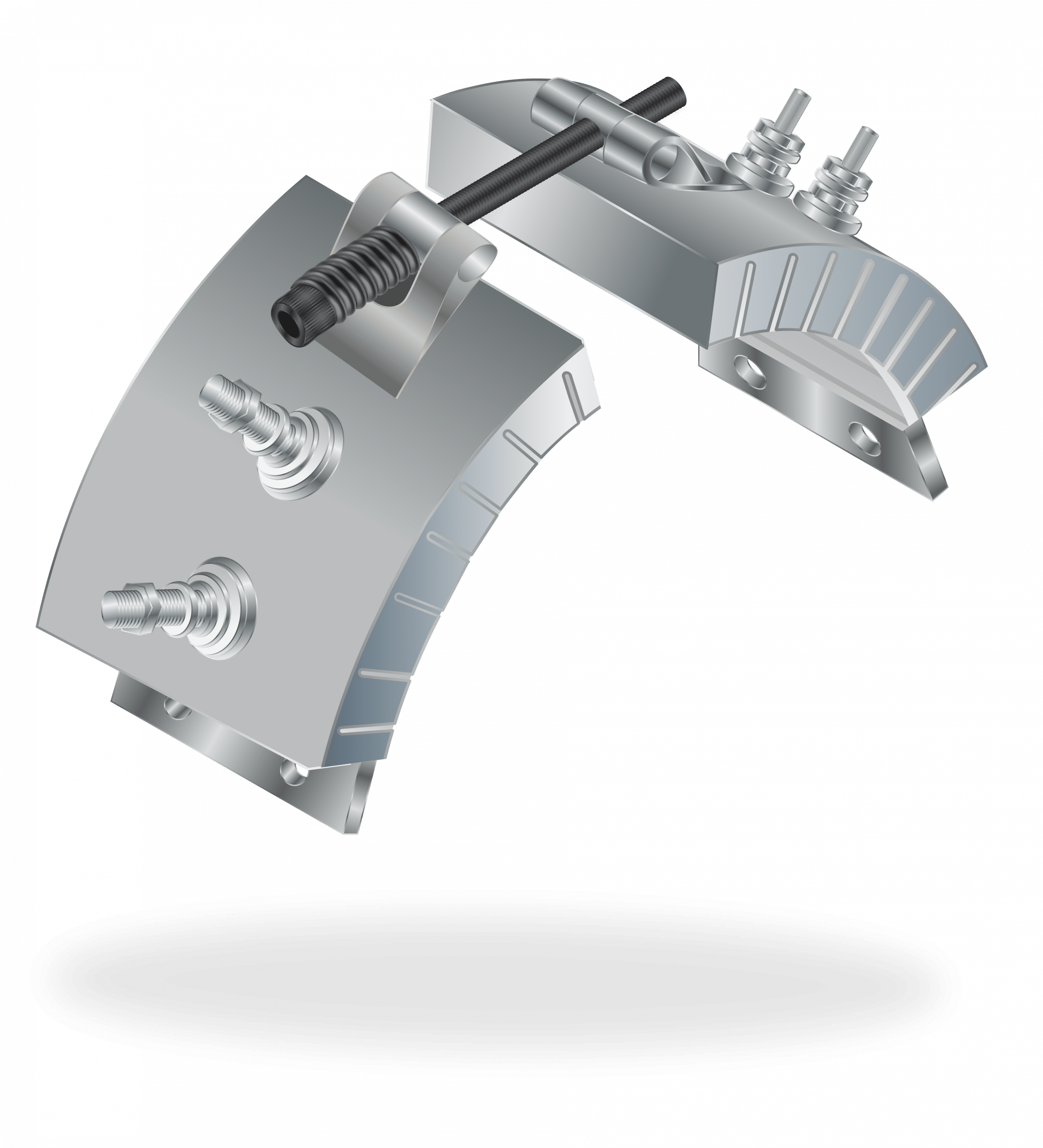 | CP | The Partial Coverage Ceramic Band heater construction is commonly used in applications requiring faster cooling or when it is not convenient to use a one-piece/two-piece band. Partial Coverage bands can be made with any insulation, clamping and termination style. |
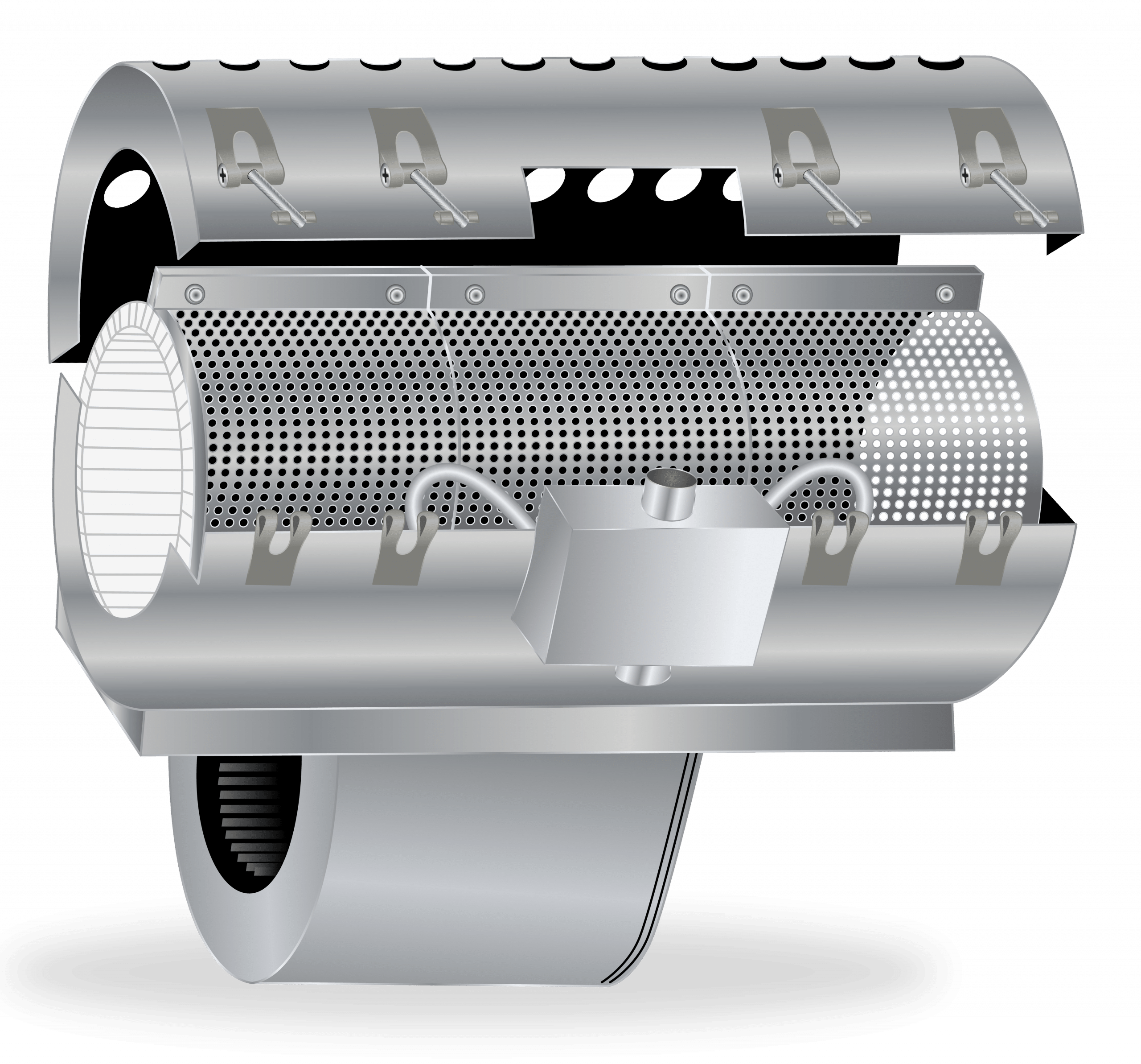  | C0 | The Ribcage / Shroud Ceramic Band heater construction features a protective outer case with an air cooling blower. This type of heater is used in applications requiring the fastest heating and cooling. This is commonly used in plastic extrusion. When a preset temperature is exceeded, the blower will turn on to reduce the process temperature. |
| Electrical Terminations | ||
| Picture | Type | Notes |
 | S1 | The Stainless Steel Braid termination offers significant flexibility and abrasion protection. The braid can exit straight, or at a 90° angle. This termination comes with a spring guard strain relief. |
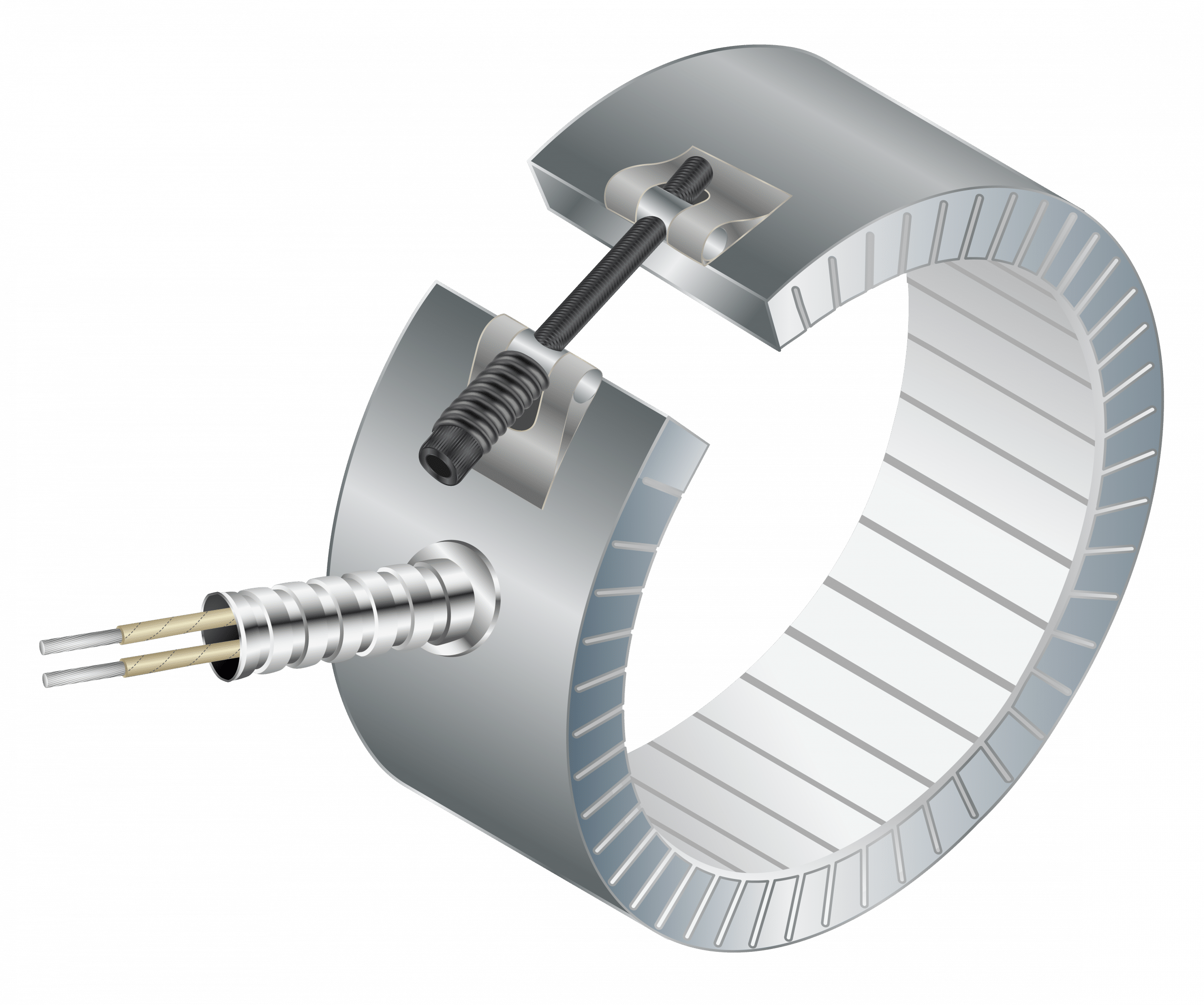 | S2 | The Stainless Steel Armor termination offers the best mechanical and abrasion protection. The armor can exit straight, or at a 90° angle. |
| TS | The Screw Terminals / Post Terminal termination comes with 2, 3, or 4 terminals (depending on the number of phases and ground) placed opposite the gap, near the gap, or on either side of the gap. |
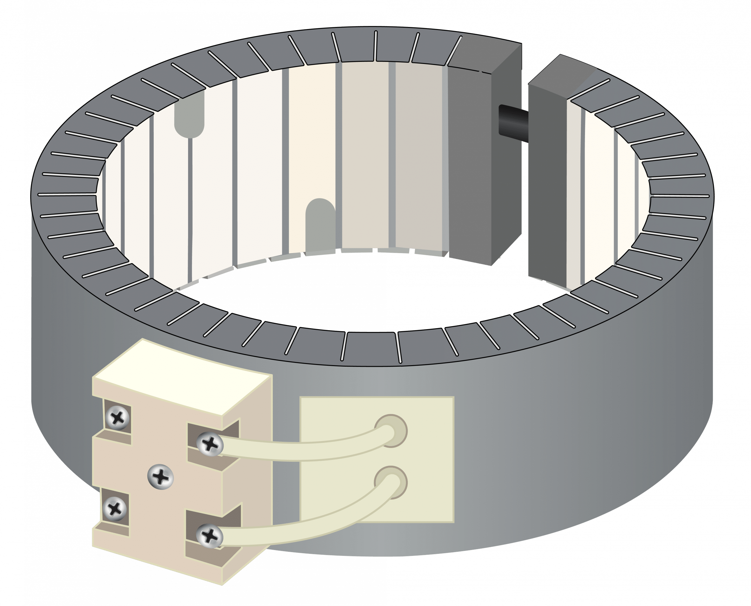 | TC | The Ceramic Terminal Block termination features an easy-to-connect high-temperature terminal block. Base wire or fork terminals can be connected. The terminal block will be placed as per the customers’ requirements. |
 | TB | The Terminal Box termination is a protective box that houses post terminals and has a knock-out hole to allow easy accessibility. The terminal box can be placed anywhere on the heater. Custom terminal boxes are also available. |
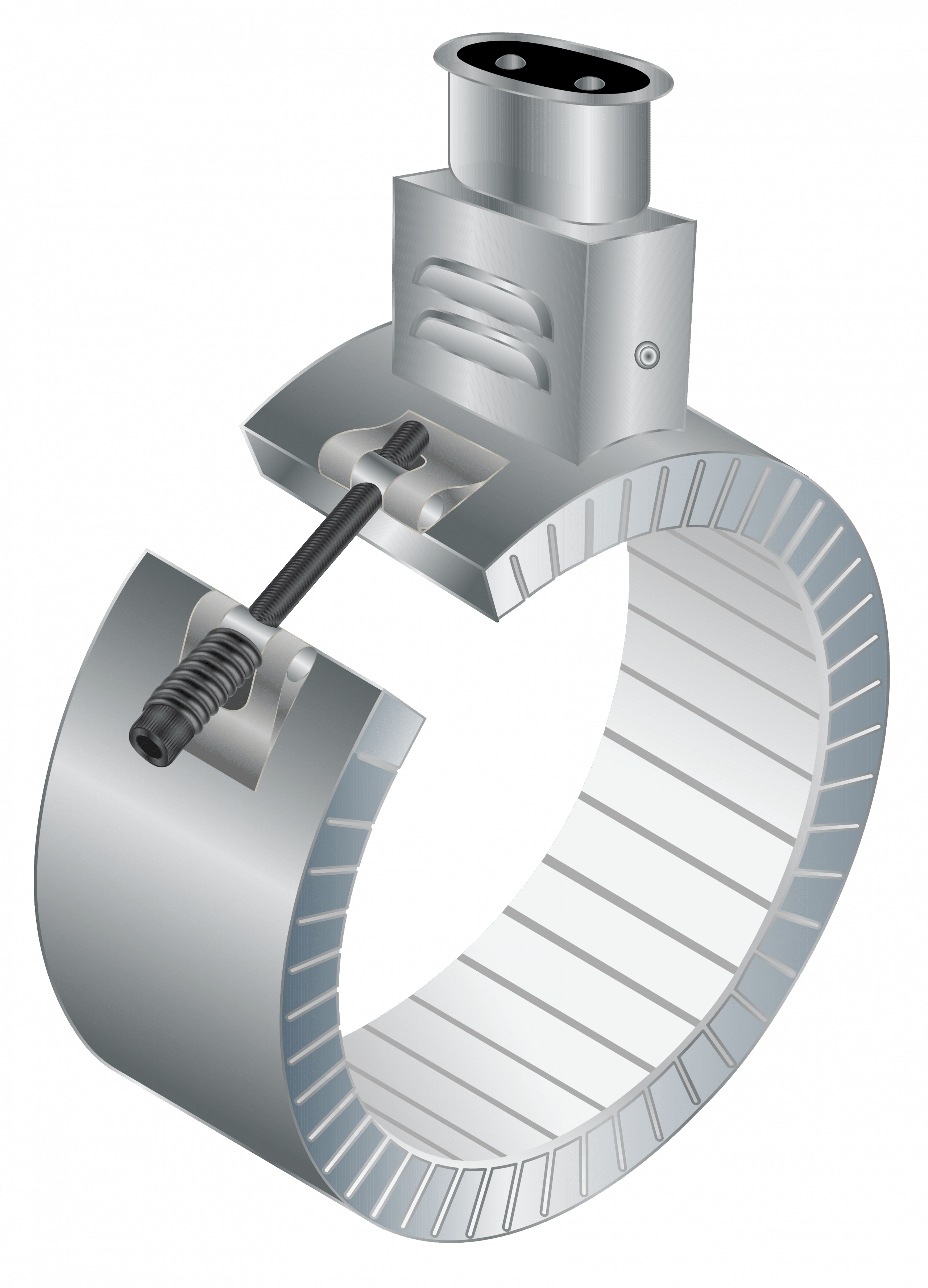 | TBE | The Euro Plug Terminal Box termination features a quick disconnect plug to eliminate the dangers associated with live wiring and exposed terminals. |
| Insulation Option | Insulation Thickness / Band Thickness | Best for | Energy Savings |
| Standard | 1/4″ Insulation – 5/8″ Overall | Lower Temp / Lower Wattage Applications | Good |
| Extra Insulation | 1/2″ Insulation – 7/8″ Overall | Medium-High Temp / Medium-High Wattage Applications | Great |
| Insulation Max | 3/4″ Insulation – 1-1.25″ Overall | High Temp / High Watt Applications (up to 1600°F) | Excellent |
Always use utmost caution when handling any electrical components to prevent electric shock and injuries.
Read and understand the instructions before beginning installation.
Note that ceramic band heaters heat through radiation and conduction and do not require the same securing methods as other band heater designs.